- Posts: 25
- Thank you received: 0
tube amps
- flinnt45
-
 Topic Author
- Offline
- Junior Member
-

Less
More
14 years 5 months ago #14913
by flinnt45
Replied by flinnt45 on topic tube amps
Hey Narinder
sorry for the triple post
Have no idea why this occured....Gremlins? anyway please see
the attached Gec circuit image...is this the circuit
if so this is AB1...ULTRALINEAR and could produce 100 watts
more if individual bias adjustment were provided for each tube
sorry for the triple post
Have no idea why this occured....Gremlins? anyway please see
the attached Gec circuit image...is this the circuit
if so this is AB1...ULTRALINEAR and could produce 100 watts
more if individual bias adjustment were provided for each tube
- NITZ V1505
-

- Offline
- Senior Member
-

Less
More
- Posts: 78
- Thank you received: 0
14 years 5 months ago #14915
by NITZ V1505
Replied by NITZ V1505 on topic tube amps
Thats the circuit Ian but with more valves in the o/p stage. I always assumed it was class B :oops: . Ian could it be class AB2?
Jack Ruby's monster amp must have weighed a ton!!!!! Would have loved to have heard it.
Jack Ruby's monster amp must have weighed a ton!!!!! Would have loved to have heard it.
Please Log in or Create an account to join the conversation.
- flinnt45
-
 Topic Author
- Offline
- Junior Member
-

Less
More
- Posts: 25
- Thank you received: 0
14 years 5 months ago #14918
by flinnt45
Replied by flinnt45 on topic tube amps
hey Narinder
This circuit is definatley AB1 and ultra linear
You can see this by the lack of a driver transformer or additional cathode followers
the first tube in the circuit is the input/phase splitter...the second is the driver/cathode
follower...if this was AB2...Or B for that matter the connection from the cathode follower
to the grids of the output tubes would be direct...no coupling capacitor...and each output tube would require
its own cathode follower driver tube...another four tubes in total as each tube is really 2..a pair of triodes
in the same envelope .....A good example of Class B output stage topography Are the Altec curcuits
one which uses the 811a triode to develop 170 watts from a pair
Please Log in or Create an account to join the conversation.
- flinnt45
-
 Topic Author
- Offline
- Junior Member
-

Less
More
- Posts: 25
- Thank you received: 0
14 years 5 months ago #14919
by flinnt45
Replied by flinnt45 on topic tube amps
hey narinder
please see the attached image of the altec curcuit mentioned
typical class b
please see the attached image of the altec curcuit mentioned
typical class b
- NITZ V1505
-

- Offline
- Senior Member
-

Less
More
- Posts: 78
- Thank you received: 0
14 years 5 months ago #14928
by NITZ V1505
Replied by NITZ V1505 on topic tube amps
I should have known that without an interstage transformer and with the coupling cap between the cathode follower that it wasnt class B or AB2.
Must read that GEC book again, its been a good few years. As you can probably tell Im no expert but I have a love for valve equipment.
Thanks for the Altec circuit. smiley20
Must read that GEC book again, its been a good few years. As you can probably tell Im no expert but I have a love for valve equipment.
Thanks for the Altec circuit. smiley20
Please Log in or Create an account to join the conversation.
- Daz
-

- Offline
- Senior Member
-

Less
More
- Posts: 43
- Thank you received: 1
14 years 5 months ago #14934
by Daz
Replied by Daz on topic tube amps
Hi Ian
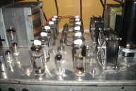
I never got to work on anything as monterously powerfull as your amps. They look awsome and i'm sure come with an equaly awsome electrical consumption :shock: I cut my valve teeth on Marshal/Vox/Fender/Sound City and good old Orange guitar amps. More years ago than I am prepaired to admit to :lol: Nothing over about 120W.
One of the comments I always used to get with valve Bass Guitar amp owners was that their amp always seemed to produce more volume per watt than the solid state versions.
On doing some research into why. The answer that frequently came up was that resistance in the Valve units output transformer secondary winding, reduced the amps Damping Factor when compared to a Transistor OP stage. The speaker being less tightly controlled actually seemed to be an advantage in this application.
Do you think this would still be true of your far more up to date valve designs or has this been engineered out :
:
Daz
I never got to work on anything as monterously powerfull as your amps. They look awsome and i'm sure come with an equaly awsome electrical consumption :shock: I cut my valve teeth on Marshal/Vox/Fender/Sound City and good old Orange guitar amps. More years ago than I am prepaired to admit to :lol: Nothing over about 120W.
One of the comments I always used to get with valve Bass Guitar amp owners was that their amp always seemed to produce more volume per watt than the solid state versions.
On doing some research into why. The answer that frequently came up was that resistance in the Valve units output transformer secondary winding, reduced the amps Damping Factor when compared to a Transistor OP stage. The speaker being less tightly controlled actually seemed to be an advantage in this application.
Do you think this would still be true of your far more up to date valve designs or has this been engineered out
 :
:Daz
Please Log in or Create an account to join the conversation.
- flinnt45
-
 Topic Author
- Offline
- Junior Member
-

Less
More
- Posts: 25
- Thank you received: 0
14 years 5 months ago #14945
by flinnt45
Replied by flinnt45 on topic tube amps
Hey Darren
The resistance of the output transformers secondary...impedance with just onepair of tubes is not usually good which leads to poor damping and bouncy bass...which leads to distortion and an apparent louder sound
so its the tubes and not the output transformer if you are using more than two pairs parralled up the output impedance beggins to drop to a small fraction of an ohm...providing for very good damping and much more accurate bass reproduction...allthough the distortion will still be available when the amplifier is driven into clipping...which with tubes is very gentle and with tube amps is mostly composed of second and third harmonics
which the ear finds not unpleasant....if you see a sine wave of a tube amp clipping it is still rounded it just changes shape gently at clip...so up to 50% more distorted power is available for the same wattage...hence why the tube amp seems louder
when a transistor amp clips it clips hard as the feed back loop is broken and is composed of higher order harmonics which sound harsh...you turn your amp down ..the distortion is unusable so to speak...transistor amps have high levels of negative feed back generally which removes all distortion but tends to shut the sound in a bit by comparison
my amps have 17db of feedback and remain stable....most tube amps commonly have 10 to 14 db...bit more feed back= lower output impedance=better bass....distortion still available when i need it...just cleaner sounding...so not engineered out....just more efficient....the one thousand watt amp uses 10 amps of current at swith on...not bad consumption actually....
Please Log in or Create an account to join the conversation.
- Daz
-

- Offline
- Senior Member
-

Less
More
- Posts: 43
- Thank you received: 1
14 years 5 months ago #14953
by Daz
Replied by Daz on topic tube amps
Thanks Ian
So the poor damping is a result of the output stage/feedback side rather than the transformers ability to present a low impeadance to its load, Ok I get that.
Schoolboy error on impeadance :oops:
As the job of the output transformer is primaraly to match impeadance would that also suggest that the amps using single pair ( for say 50W output) and not having a great deal of feedback were just not well designed in the first place. The designers going more for "how mutch can we get out" rather than better quality sound : I realise that the soft soggy distortion was perhaps unintentional from the point of view of the amp designers back in the day. It did however become a sought after sound for guitarists.
I have seen the softer clip you refer to when load testing amps on a scope (as well as hearing them singing. They realy seemed to come alive). If I remember this was only realy soft at the onset of clipping. If you drove them further into distortion the wave would square up. Not nearly as dramatic as seeing clipping on a solid state amp tho.
So when you get to a serious number of valve pairs, 10 for example are you still looking at the effect of the valve outputs as being the major limitation on damping factor or would the design/quality of the output TX come into play. I assume that you would eventually reach a point where the losses in the TX would become a limiting factor. Or, do you naturaly counter this by having heavier gauge wire/More meat in the core construction of the Transformer to handle the extra power. Just how low you could go with the overall output impeadance of the amp : Can you get close to a solid state amp of similar power
  :
:
Oh and is that 10A at idle or when at full output :
:
Lots of questions but its fun to learn more about these types of amp. Very few people know mutch about valve these days and my own knowledge is fairly rusty smiley32
Thanks
Daz
So the poor damping is a result of the output stage/feedback side rather than the transformers ability to present a low impeadance to its load, Ok I get that.
Schoolboy error on impeadance :oops:
As the job of the output transformer is primaraly to match impeadance would that also suggest that the amps using single pair ( for say 50W output) and not having a great deal of feedback were just not well designed in the first place. The designers going more for "how mutch can we get out" rather than better quality sound
 : I realise that the soft soggy distortion was perhaps unintentional from the point of view of the amp designers back in the day. It did however become a sought after sound for guitarists.
I have seen the softer clip you refer to when load testing amps on a scope (as well as hearing them singing. They realy seemed to come alive). If I remember this was only realy soft at the onset of clipping. If you drove them further into distortion the wave would square up. Not nearly as dramatic as seeing clipping on a solid state amp tho.
So when you get to a serious number of valve pairs, 10 for example are you still looking at the effect of the valve outputs as being the major limitation on damping factor or would the design/quality of the output TX come into play. I assume that you would eventually reach a point where the losses in the TX would become a limiting factor. Or, do you naturaly counter this by having heavier gauge wire/More meat in the core construction of the Transformer to handle the extra power. Just how low you could go with the overall output impeadance of the amp
 : Can you get close to a solid state amp of similar power
  :
:Oh and is that 10A at idle or when at full output
 :
:Lots of questions but its fun to learn more about these types of amp. Very few people know mutch about valve these days and my own knowledge is fairly rusty smiley32
Thanks
Daz
Please Log in or Create an account to join the conversation.
- flinnt45
-
 Topic Author
- Offline
- Junior Member
-

Less
More
- Posts: 25
- Thank you received: 0
14 years 5 months ago #14965
by flinnt45
Replied by flinnt45 on topic tube amps
hey Daz
guitar amps are designed with low feedback and poor output transformers deliberatly
to produce more distortion...which gives them thier distinct sound
the same output transformer on a fifty watt hifi amp would be twice the size
with a much lower roll off at low frequency typically 20hz-3db
so much less distortion in theory
and yes older amp designes are less well developed...not necasarilly.poorly designed
within the components and materials available at the time and with the advent of transistors in the late
60,s development wk dried up allmost overnight...
the advent of better components and materials available now means that valve amps can be built that equal
and in many cases better the performance of thier transistor brethren
out put impedance is directly affected by the number of output tubes, each pair added halves the output
impedance my big amps output impedance is .0175 ohm...without feedback it would still be under 1 ohm..just
this allows for great damping...allso has the effect of lowering the reflected plate to plate impedance seen by the
output transformer primary...pl509 has p-p impedance of 3500k... pair...12 has p-p impedance of 600ohms
making winding the output transformers winding ratio much lower...much easier to wind a quality tx with thick wire
and with grain orientated slicone steel laminations losses are much lower than previously available..so more
tubes better everything!!
.current for this output stage on sinewave is 2.4 amps..she uses 10 amps at startup 7amps
in normal use..output+input driver circuit regulators and filaments...perhaps another 4.5 amps
hope i have answered your questions fully Daz
Best...Ian
Please Log in or Create an account to join the conversation.
- bitzo
-

- Offline
- Platinum Member
-

Less
More
- Posts: 637
- Thank you received: 1
14 years 5 months ago #14971
by bitzo
Replied by bitzo on topic tube amps
Great posts, very interesting at all.
In your experience with your 1050w valve amp... how often did you change the valve?
In your experience with your 1050w valve amp... how often did you change the valve?
Please Log in or Create an account to join the conversation.
Time to create page: 0.359 seconds